Air Blown Cables Introduction (part1)

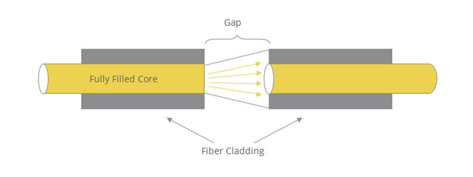
Basics of Fiber Optic Attenuator
August 15, 2021
Harmonic power distortions, radio frequency interference and electromagnetic interference are all examples of electrical problems that may have a significant adverse effect on the performance of telecommunications and other types of high-speed signaling systems. A possible remedy for such problems is to consider converting the signaling media from copper to fiber optic cables. Transporting photons instead of electrons, fiber optic cables offer 100% immunity from all forms of electrical interference. In addition, fiber optic cables can support much higher bandwidths, for longer distances with increased reliability when compared with copper cables. Implementing or converting to fiber optics has become increasingly easier. Today nearly all manufacturers of high speed communications equipment and other signaling systems offer fiber optic interfaces as a standard product. New connector and splicing technology has made fiber optic cable termination and testing as cost-effective as terminating most types of copper cables. What is more, advancements such as the development of “air-blown” installation methods have resulted in a quantum reduction in fiber optic cable installation, maintenance and replacement costs. Using “air-blown” technology, fiber optic cables may be installed, relocated or replaced in a small fraction of the time required to install most types of copper cables. (1)
The demand for next generation broadband services such as 5G and Internet of Things (IoT) is highly expanding. In order to achieve the next generation broadband services, it is required to install the fiber optic cables into the limited duct spaces. For this reason, development of small diameter and high fiber packing density of optical cables has been actively conducted. By the way, one of the cable installation methods is the blowing technique into microduct with compressed air.(2) The air-blown fiber (ABF) system that was introduced by British Telecom Research Laboratories in 1983 has become well known for the advantages of its installation process, which involves blowing an optical-fiber unit into an empty tube with compressed air.(4) This technique is commonly applied especially in highly populated regions in Europe. In general, the conventional microduct cable has primarily adopted a central strength member and stranded small loose tube design (2)
Blown Fiber is a technology with four main components namely products, blowing devices, optical fiber bundles, and terminating/connecting hardware. This technology results in more cost-efficient, more flexible designs, better work costs in installation, termination and cheaper testing compared to conventional optical fiber deployment technology.(3)

These issues indicate the emergence of two sectors in the cable industry, on the one hand, the production and introduction of micro-cables with various capacities and low diameters, and on the other hand, the production and introduction of micro-ducts with multiple capacities and capabilities. It is clear that the quality of the final implementation of cable routes with this method depends on the quality and correct operation of both factors. In contrast, micro-duct factories compete by expressing their relative advantages in reducing friction, increasing load and pressure tolerances, and increasing the service life of products using high-quality raw materials.
When deploying a fiber network, traditional trenching methods can be expensive and time-consuming – and cause extensive disruption to the local area. In a city, for example, streets have to be closed while they are dug up – annoying residents, drivers and local authorities. Costs for labour, permits and restoration fees are high, adding to budgets and even making some projects uneconomic.
Consequently, many installers are now switching to micro trenching (also known as slot-cut trenching). This offers substantial benefits over traditional methods as it involves using a diamond circular saw to cut a 0.75 – 1.5 inch wide, 4 inch deep trench. Microduct is installed in the bottom of the trench and it is then backfilled and sealed, speeding up the project.
By comparison, traditional trenches are at least 12 inches wide, in order to fit the size of the smallest excavator buckets, and deployments take more passes to backfill. These factors combined mean that micro trenching is typically 60 per cent cheaper than traditional excavations, as well as being much less disruptive to the urban environment.
The question is, where can we use Micro trenching? The answer is in FTTH, Long haul, Back haul, Smart cities, DAS antenna installation, Node B & Enode B sites and more!
References:
(1) Gorrell, P. (1996, October). Fiber optic” air-blown” solutions. In Wescon/96 (pp. 189-193). IEEE.
(2) SHIMIZU, S., MUKAI, O., NAMAZUE, A., & OSATO, K. (2019). Air-blown Fiber Optic Cable with SWR and WTC Technologies. Fujikura Technical Review, 7.
(3) Hutomo, S. P., & Wibisono, G. (2020, April). The advantage of blown fiber technology for out site plan network deployment than conventional cabled optical fiber system in Depok apartment project. In Journal of Physics: Conference Series (Vol. 1528, No. 1, p. 012044). IOP Publishing.
(4) Sano, H., Terasawa, Y., & Tanaka, S. (1991, February). Development of a multiple-count optical-fiber unit for an air-blown fiber system. In Optical Fiber Communication Conference (p. WL7). Optical Society of America.