Basics of Fiber Optic Attenuator

Air Blown Cables Introduction (part1)
August 15, 2021Dozor DLP
November 5, 2022
To strengthen the signal power in fiber optic links is sometimes needed to achieve long-haul data transmission, however, under certain circumstances, too much signal power can overload fiber optic receivers and does harm to the optical network. To reduce the power in fiber links, fiber optic attenuators are leveraged. Here we will shed light on fiber optic attenuator types, working principles, and applications, which will help you gain a comprehensive understanding of fiber optic attenuator.
What Are Fiber Optic Attenuators?
Fiber optic attenuator, also called optical attenuator, is a passive device used to reduce the power level of an optical signal. Owing to that too much light can make a fiber optic receiver saturated, the light power must be reduced by using fiber optic attenuator to achieve the best fiber optic system performance. Generally, multimode systems do not need attenuators as the multimode sources, even VCSELs, rarely have enough power output to saturate receivers. Instead, single-mode systems, especially the long-haul DWDM network links, often need to use fiber optic attenuators to adjust the optical power during the transmission
Working Principles of Fiber Optic Attenuators
Optical attenuator achieves the desired attenuation in optical fiber links according to different principles, including gap-loss principle, absorptive principle, or reflective principle.
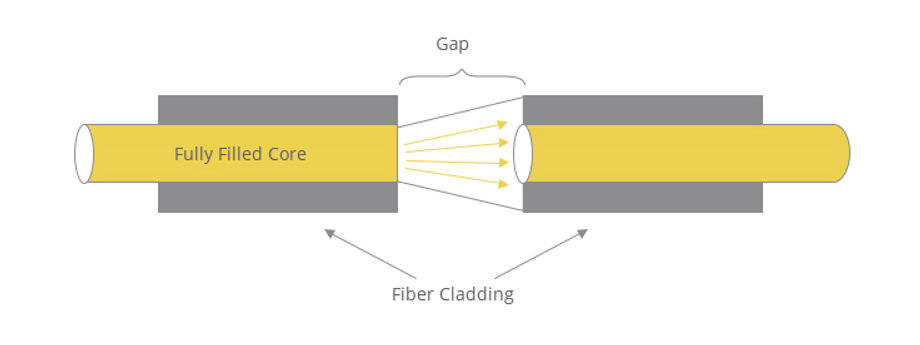
Gap-loss Principle
The gap-loss principle reduces the optical power level by inserting the device in the fiber path with an in-line configuration. Gap-loss attenuators are used to prevent the saturation of the receiver and are placed close to the transmitter. Gap-loss attenuators use a longitudinal gap between two optical fibers so that the optical signal passed from one optical fiber to another can be reduced. This principle allows the light from the transmitting optical fiber to spread out as it leaves the optical fiber. When the light gets to the receiving optical fiber, some of the light is lost in the cladding because of a gap and the spreading occurred. These optical attenuators should be kept close to the transmitter to ensure its effective performance. To reduce the signal farther down the fiber path, an optical attenuator using absorptive or reflective techniques is more suitable.

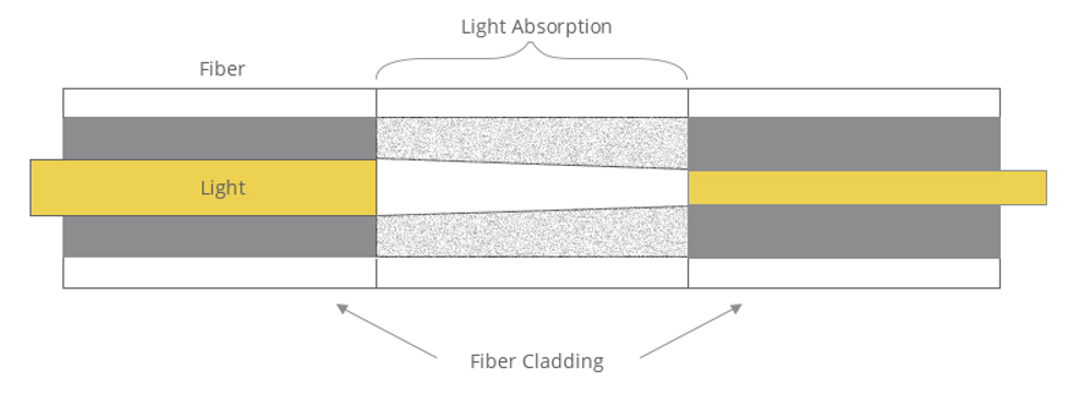
Absorptive Principle
The absorptive principle, or absorption, accounts for a fraction of power loss in optical fiber. This is caused because the optical fiber absorbs optical energy and converts it to heat. Absorptive principle can be employed to design an optical attenuator with a known reduction of power. The absorptive principle uses material in the optical path to absorb optical energy. The principle is simple but can be an effective way to reduce the power being transmitted and received.
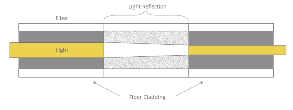
Reflective Principle
The reflective principle, or scattering, accounts for a fraction of power loss in optical fiber and also results from the imperfections of optical fiber. But in this case, it causes the signal to scatter. The scattered light inserts interference in the optical fiber, thereby reducing the amount of transmitted and received light. This principle can be employed in the planned attenuation of a signal. The material used in the fiber optic attenuator is manufactured to reflect a known quantity of the signal, thus allowing only the desired portion of the signal to be propagated.
How Many Types of Fiber Optic Attenuators Are There?
Fiber optic attenuator takes a number of different forms. You can find many optical attenuators types in the market with different classification perspectives such as the connector type, cable type, etc. Generally, they are widely accepted to be grouped as fixed optical attenuators (FOA) and optical variable attenuators (VOA).
Fixed Optical Attenuator
Fixed attenuator, as the name of which has indicated clearly, is designed to have an unchanging level of attenuation in optical fiber, expressed in dB, typically between 1dB and 30dB, such as 1dB, 5dB, 10dB, etc. Fixed optical attenuators may use a variety of principles for their functioning. Preferred optical attenuators often use either doped fibers, or misaligned splices, or total power while non-preferred attenuators often use gap loss or reflective principles.
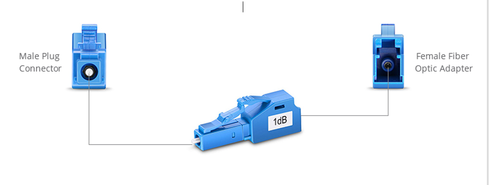
As shown in the figure below, fixed value attenuators consist of in-line type and connector type. In-line type looks like a plain fiber patch cable. The in-line type optical attenuators are incorporated into patch cables. Connector type attenuator looks like a bulkhead fiber connector. Usually, it has a male plug connector at one side to allow fiber attenuator to be plugged directly into receiver equipment or adapters in patch panel, and at the other side there is a female type fiber optic adapter to allow the patch cords to plug in. There are also female to female optical attenuators, which can be used as adapters and attenuators at the same time. Their applications include telecommunication networks, optical fiber test facility, Local Area Network (LAN) and CATV systems.
Optical Variable Attenuator
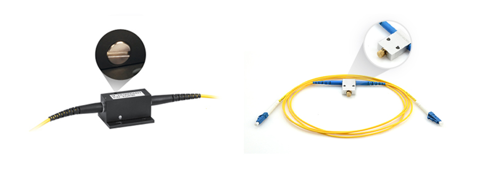
Optical variable attenuator, or variable optical attenuator (VOA), generally uses a variable neutral density filter. VOA is generally used for testing and measurement, but it is also widely adopted in Erbium-Doped Fiber Amplifier (EDFA) for equalizing the light power among different channels. It has advantages of being stable, wavelength insensitive, mode insensitive, and offering a large dynamic range.
Basically, there are two types of optical variable attenuator: stepwise variable attenuator and continuously variable attenuator. Stepwise variable attenuator can change the attenuation of the signal in known steps such as 0.1dB, 0.5dB or 1dB. Continuously variable optical attenuator produces a precise level of attenuation with flexible adjustment. Thus, operators are able to adjust the attenuator to accommodate the changes required quickly and precisely without any interruption to the circuit.
Single Mode and Multimode Fiber Optic Attenuator
Since fiber optic attenuators can be used in two types of fiber cables, single mode and multimode, optical attenuators can be classified into single mode type and multimode type. Fiber optic attenuators are usually used in single mode long-haul applications. Accordingly, the commonly used type is also single mode type. However, although fiber optic attenuators are normally used for single mode, there are also multi-mode fiber optic attenuators available to mate with multi-mode fiber cables. When choosing one type of optical attenuator over another one, it is necessary to consider the attenuation range and the wavelength.
When to Use Fiber Optic Attenuators?
Attenuators are used when the signal arriving at the receiver is too strong and may overpower the receiving elements, and attenuators can be used for testing the power level margins. Overall, there are two scenarios where optical attenuators can play their roles:
- In fiber optic power level testing, attenuators are used to temporarily add a calibrated amount of signal loss in order to test the power level margins in a fiber optic system.
- Optical attenuators are permanently installed in a fiber optic link to properly match signal levels at transmitter and receiver.
How to Use Fiber Optic Attenuators in Data Link?
For single-mode applications, especially analog CATV systems, the most important parameter after the correct loss value is return loss or reflectance. Many types of optical attenuators (especially gap loss types) suffer from high reflectance, so they can adversely affect transmitters just like highly reflective connectors.
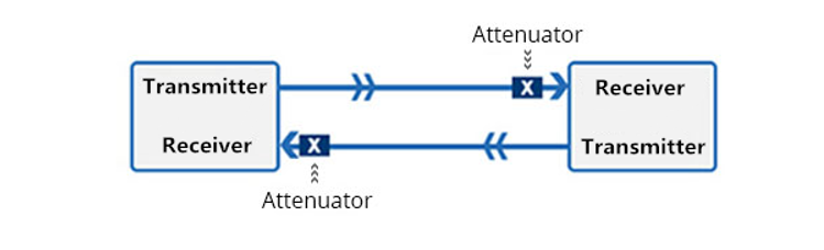
Choose an attenuator with good reflectance specifications, and always install the attenuator at the receiver end of the link as shown above. This is because it’s more convenient to test the receiver power before and after attenuation or while adjusting it with your power meter at the receiver, plus any reflectance will be attenuated on its path back to the source.
Test the system power with the transmitter turned on and the optical attenuator installed at the receiver and using an optical power meter set to the system operating wavelength. Check to see whether the power is within the specified range for the receiver. If the optical power is higher or lower than the configuration required, the optical attenuators should be changed to adjust the power again.
Conclusion
Fiber optic attenuator is an essential passive component in the optical communication system. The innovation in the fiber optic industry never ceases, and fiber optic attenuators will evolve to have lower cost, faster response time, and enhanced integration of hybrids with other optical communication devices.
Reference : FS Community